Lesson 3 - Assemblies
Inserting Parts and Assemblies
To access the same parts we have in the ftc closet, we have the FTC Parts List. This section will explain how to insert parts from that folder or from any of your other documents.
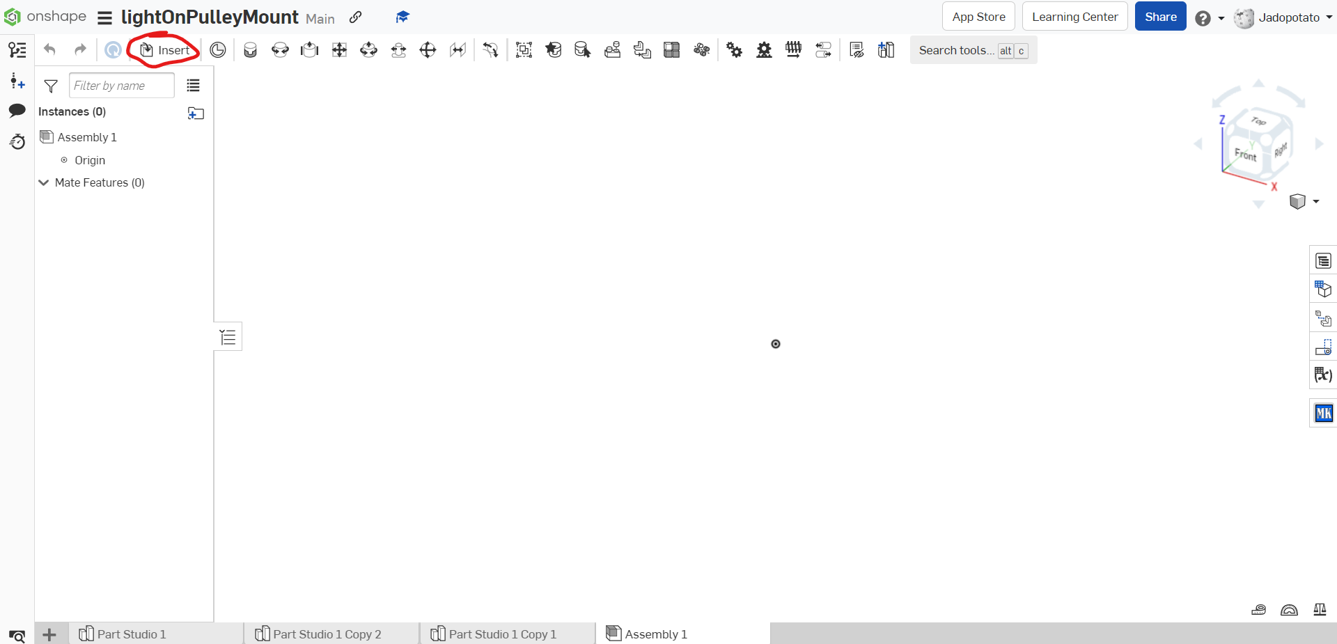
To insert a part, first click the “Insert” button at the top left of the screen. Alternately, you can press the “s” key and click the top left image on the panel that pops up.
The “Inserting Parts and Assemblies” window starts on the “Current Document” tab by default, so if you are only trying to import a part or assembly from the document you are currently on, you can skip to Inserting the Part. Otherwise, if you are trying to insert a part or assembly from the FTC Parts List, go to the “Other Documents” tab.

From the Other Documents tab, navigate to “FTC Robotics Parts Users”, which has most of the ftc parts supplied by major FTC part vendors such as goBILDA and REV Robotics.

From here, you can navigate through these folders to find the part you want to insert. I am going to show the way to insert a 5203 Series Yellow Jacket Planetary Gear Motor — a motor often used in our robot designs — and the exact path will be different for inserting different parts.


Inserting the Part
Once you have found the part you want to insert, click on it and move your cursor onto your assembly. A yellow preview of the item will appear on your cursor which can be inserted with a left click. When you have inserted the part, hit the check mark to confirm the insertion. Clicking the X or hitting the Esc key will result in the insertion being canceled, though a popup will allow you 30 seconds to restore the insertion and revert any accidental cancels.

Mates/Constraints
Mates are geometric constraints that define an object’s position and the ways it can move in relation to faces, edges, or vertices.
As you hover over an entity, a circle indicator will appear to indicate the actual position and alignment of the connector.


Fasten Mate
Fasten Mates are the simplest mates conceptually, and rigidly connects 2 entities with 0 degrees of freedom. When the connectors are fastened, the first connector moves to the second connector, unless the first connector is fixed in place or connected to piece that is fixed in place. To use a fasten mate, click on the icon that looks like two cylinder puzzle pieces connecting, which will make open a fasten mate window.
![]()

Click on the first connector you want to fasten, then find and select the second connector. The fasten mate will apply on the screen, and to finalize it, just click the check mark.


Revolute Mate
Revolute Mates are essential to adding motion to your assemblies, and they only allow 1 degree of freedom: rotation around the z axis. The first connector is considered the rotational point and the second is considered the stationary point. To create a revolute mate, first click the icon of a cylinder with 2 arrows curving around its sides, which opens the revolute mate window.
![]()

Select the first connector, making sure the indicator is in the center of the circular face you are applying the mate to. For the second connector do the same, remembering to make sure the indicator is on the right plane of the stationary point, and still in the center of the circular face. Once the 2 parts have connected, hit the check mark to confirm the mate.


